
CONFIGURATION INDEX
| Item | Configuration |
|---|---|
| Document | pac.html |
| Markdown source / build | pac_R02.md / B261109 |
| File revision / build | R003 / B261109 |
| Content revision / build | R002 / B261014 |
| Date | 2026-11-09 |
| Approved source application | SPOTMAP v0.9.9R01 FIX1 |
| Standalone application | n/a |
| Source display / package build | B261013 / 2026101303 |
| Standalone package build | n/a |
| Status | Prepared for project-owner review; not uploaded. |
Generic information
- The offline app help stays available even when not connected to internet.
- The online web help requires an internet connection.
- This is a reference tool only and not a substitute for knowledge, experience or approved operational data; always strictly use, adhere, follow and verify with approved operational data.
- If you do not have a FULL understanding of the tool, do not use it!
How to use the help section
🔴Disclaimer: A disclaimer is a legal statement designed to limit a company's liability or specify the boundaries of a product's warranty. It informs the user about what the product or company is not responsible for, or clarifies that certain information (like third-party software updates) is outside of the company's control. Impact: Legal/Financial. It protects the organization from lawsuits and sets realistic expectations for the product's performance or usage.
⚠️Warning: A warning alerts the user to potential hazards that could result in personal injury, death, severe data loss, or permanent damage to equipment. It is the most critical type of callout and must clearly explain the hazard, the consequences of ignoring it, and how to avoid it. Impact: High. Ignoring a warning can lead to physical harm or catastrophic system failure, or both.
🔼 Note: A note provides helpful, non-critical information to the user. It emphasizes points, clarifies steps, or offers background context that is not essential to completing the main task but improves the user's understanding. Impact: Low. Ignoring a note will not cause harm, damage, or data loss.
INTRODUCTION
Pivotal Altitude Computer calculates a pivotal reference height from the current GNSS ground speed. The live value, table, graph, and illustration help explain how the calculated height changes with ground speed.
BASIC USAGE
Open TOOLS → PIVOTAL ALTITUDE COMPUTER. No manual speed-entry or compute button is required; the card reads the existing live GNSS speed, including before the main recording starts.
1. Check the status
Read the status at the top. A fresh usable speed provides the calculation. Missing or stale speed produces dashes; a dash is not a zero-height result.
The reference curve/table covers 20–120 kt. A usable speed outside that interval keeps its actual calculated result and is labeled OUT OF RANGE rather than being forced to an endpoint.
2. Read the table and graph
The table compares GS [kts] with calculated AGL [ft]. The graph shows the same relationship. The live indicators identify the current ground speed and resulting pivotal height. In a narrow layout, the table and graph may stack or require horizontal scrolling.
3. Understand the formula
The app uses:
Pivotal height AGL [ft] = GS [kt]² / 11.3
For example, at 60 kt the calculation is 60 × 60 / 11.3 = 318.6 ft, displayed as approximately 319 ft. This is a calculation from ground speed, not a measured aircraft height above the terrain.
The displayed altitude relationship is:
Pivotal altitude AMSL [ft] = pivotal height AGL [ft] + field elevation [ft]
Field elevation is explanatory in this card. The tool does not provide a terrain elevation, accept a field-elevation entry, or measure the aircraft's actual AGL height.
4. Read the illustration and limitations
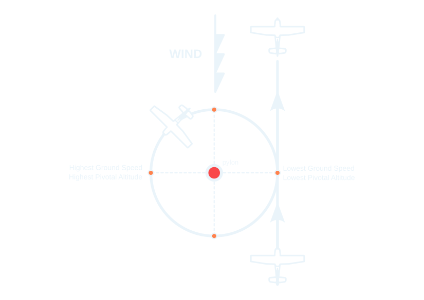
The illustration relates wind, ground speed, and calculated pivotal height around the reference point. Higher ground speed gives a higher calculated height; lower ground speed gives a lower calculated height. The speed is ground speed, not indicated or true airspeed.
⚠️Warning: A calculated pivotal height is not an instruction or authorization to descend to that height. It does not assess terrain, obstacles, aircraft limitations, weather, or applicable minimum safe altitudes. The card's regulatory reminder is background information; use the applicable current operational requirements.
5. Close the card
Tap X to return to SPOTMAP. The calculator does not change recording or create a POI. No database or internet connection is needed for the calculation when usable GNSS speed is available.
PIVOTAL ALTITUDE — THEORY AND REFERENCE
Pivotal Altitude
Geometry, Flight Mechanics, Sight References, and Operational Context
Source: Pivotal_Altitude_R02.tex · Original document date: 7 October 2026.
Abstract
Pivotal altitude is the altitude at which, for a given groundspeed, a ground reference appears to remain fixed on a sight line parallel to the airplane’s lateral axis while the airplane turns about that reference. This note develops the FAA rule of thumb from first principles, explains why bank angle cancels from the final result, examines custom sight references on high-wing airplanes, and distinguishes the training concept from superficially similar operational orbiting tasks. A final section records, as an unresolved historical hypothesis, the calibrated-looking strut and window markings observed on military Max Holste MH.1521M Broussard aircraft.
Contents of this chapter
- 1. FAA concept and purpose
- 2. Where the formula comes from
- 3. Rotating-frame derivation
- 4. Why bank angle disappears
- 5. From to the FAA knot formula
- 6. Wind and the actual maneuver
- 7. Calibrated sight references on a high-wing airplane
- 8. What pivotal altitude is, and is not, operationally
- 9. The Max Holste MH.1521M Broussard markings: an open question
- 10. Summary
- References
1. FAA concept and purpose
The FAA describes the altitude appropriate for eights on pylons as the pivotal altitude. For a given groundspeed, it is the altitude at which the projected visual reference line to the pylon appears to pivot. The FAA’s useful mental model is a taut line from the pilot’s eye to the pylon that remains parallel to the airplane’s lateral axis while the airplane turns around the pylon. The maneuver develops precise aircraft control, wind awareness, coordination, and division of attention between the flightpath and an external reference [1].
The FAA rule of thumb is
where is groundspeed and is height above the pylon. If an MSL altitude is desired, the local terrain elevation is added to the AGL result [1].
Table 1. Selected pivotal altitudes using Eq. 1.
| Groundspeed (kt) | Pivotal altitude (ft AGL) |
|---|---|
| 60 | 319 |
| 70 | 434 |
| 80 | 566 |
| 90 | 717 |
| 100 | 885 |
| 110 | 1,071 |
| 120 | 1,274 |
| 130 | 1,496 |
The dependence is quadratic. A 10% increase in groundspeed produces approximately a 21% increase in pivotal altitude. This is why wind matters strongly during the maneuver: the relevant speed is groundspeed, not indicated or true airspeed.
2. Where the formula comes from
2.1. Geometry of the sight line
Consider an ideal coordinated, level turn around a pylon on level ground. Let be the horizontal radius from the pylon to the airplane, the airplane’s height above the pylon, and the bank angle. If the eye-to-pylon sight line is parallel to the airplane’s lateral axis, the lateral axis is banked downward toward the pylon by the same angle . Figure 1 gives the cross-sectional geometry.
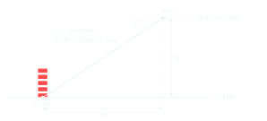
Figure 1. Ideal pivotal-altitude geometry in the vertical-radial plane.
The right triangle gives
Geometry alone does not yet determine : it relates height, radius, and bank.
2.2. Dynamics of a coordinated level turn
For a coordinated level turn at speed , the vertical component of lift balances weight and the horizontal component supplies centripetal acceleration:
Dividing gives
For the ideal no-wind derivation, is also the groundspeed. In operational use, pivotal altitude is evaluated from actual groundspeed. Combining Eqs. 2 and 5,
3. Rotating-frame derivation
Attach a rotating frame to the airplane’s orbit: radially outward, tangentially along the flightpath, and upward. Let the orbital angular rate be . Then
The airplane’s inertial acceleration is . Newton’s second law gives
so
The lift vector is normal to the wing plane. Consequently the wing/lateral-axis direction in the vertical-radial plane is perpendicular to , giving
The pylon sight geometry requires , hence
Using Eq. 7,
The rotating-frame formulation makes clear that sight-line geometry and centripetal acceleration are two views of the same angular motion.
4. Why bank angle disappears
Bank angle matters locally; it simply appears twice and cancels. Geometry requires , while coordinated-turn dynamics require
Substitution gives . A steeper bank creates both a steeper downward lateral sight line and a smaller turn radius. A shallower bank does the opposite. Figure 2 illustrates this family of solutions.
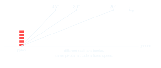
Figure 2. At fixed groundspeed, different coordinated bank angles correspond to different radii but the same pivotal altitude.
Table 2 gives the ideal coordinated-turn ground radius for combinations of bank angle and groundspeed, assuming no wind, level flight, and a circular ground track. Values are rounded upward to the next whole foot, using . In wind, groundspeed alone is not sufficient to determine the actual turn radius because air-relative acceleration and ground-track curvature differ.
Table 2. Ideal ground-turn radius (ft), rounded upward, by bank angle and groundspeed (kt); no wind, coordinated level turn.
| Bank angle (°) / GS (kt) | 20 | 30 | 40 | 50 | 60 | 70 | 80 | 90 | 100 | 110 | 120 |
|---|---|---|---|---|---|---|---|---|---|---|---|
| 5 | 405 | 911 | 1,620 | 2,531 | 3,644 | 4,959 | 6,477 | 8,198 | 10,121 | 12,246 | 14,574 |
| 10 | 201 | 452 | 804 | 1,256 | 1,808 | 2,461 | 3,214 | 4,068 | 5,022 | 6,076 | 7,231 |
| 15 | 133 | 298 | 529 | 827 | 1,190 | 1,620 | 2,115 | 2,677 | 3,305 | 3,999 | 4,759 |
| 20 | 98 | 219 | 390 | 609 | 876 | 1,192 | 1,557 | 1,971 | 2,433 | 2,944 | 3,503 |
| 25 | 76 | 171 | 304 | 475 | 684 | 931 | 1,216 | 1,538 | 1,899 | 2,298 | 2,735 |
| 30 | 62 | 139 | 246 | 384 | 553 | 752 | 982 | 1,243 | 1,534 | 1,856 | 2,209 |
| 35 | 51 | 114 | 203 | 317 | 456 | 620 | 810 | 1,025 | 1,265 | 1,531 | 1,821 |
| 40 | 43 | 95 | 169 | 264 | 380 | 518 | 676 | 855 | 1,056 | 1,277 | 1,520 |
| 45 | 36 | 80 | 142 | 222 | 319 | 434 | 567 | 718 | 886 | 1,072 | 1,275 |
| 50 | 30 | 67 | 119 | 186 | 268 | 365 | 476 | 602 | 743 | 899 | 1,070 |
| 55 | 25 | 56 | 100 | 155 | 224 | 304 | 397 | 503 | 620 | 751 | 893 |
| 60 | 21 | 47 | 82 | 128 | 185 | 251 | 328 | 415 | 512 | 619 | 737 |
| 65 | 17 | 38 | 67 | 104 | 149 | 203 | 265 | 335 | 413 | 500 | 595 |
| 70 | 13 | 30 | 52 | 81 | 117 | 158 | 207 | 262 | 323 | 390 | 465 |
As , the required radius tends to infinity. As , the ideal radius tends to zero while load factor tends to infinity. Neither limit is a practical steady turn.
5. From to the FAA knot formula
One knot equals 1.68781 ft/s, and standard gravitational acceleration is approximately 32.174 ft/s2. With in knots,
Thus “11.3” is primarily a unit-conversion constant combined with gravitational acceleration. For groundspeed in miles per hour, the FAA gives the analogous approximation
6. Wind and the actual maneuver
Wind changes groundspeed around the maneuver, so the appropriate pivotal altitude changes continuously. If groundspeed rises from 80 kt to 120 kt, pivotal altitude rises from approximately 566 ft to 1274 ft AGL. The pilot therefore does not calculate one altitude and hold it throughout an eight-on-pylons maneuver.
The visual reference is the practical sensor. The FAA describes a too-low condition as the pylon moving behind the reference and a too-high condition as the pylon moving ahead of the reference [1]. The pilot corrects altitude while maintaining coordinated flight.
7. Calibrated sight references on a high-wing airplane
7.1. An ideal lateral-axis sight
Consider a high-wing airplane such as an Aviat Husky. With the airplane stationary and level, establish a horizontal line through the pilot’s normal eye position and perpendicular to the longitudinal axis. A fixed visual marker can then be located so that, from the normal seated eye position, the eye-to-marker ray lies on that lateral line (Fig. 3).
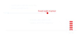
Figure 3. Concept of a calibrated eye-to-marker lateral sight reference. The external marker shown is conceptual; an actual aircraft modification requires appropriate airworthiness consideration.
In flight, if the pylon remains visually stationary behind this marker, the geometry closely implements the ideal definition of pivotal altitude. It does not force one unique bank angle or radius. At a given groundspeed it indicates the relationship among altitude, bank, radius, and coordination.
Practical errors include head-position parallax, pitch attitude and angle-of-attack offsets, wing flex and vibration, terrain elevation, and slip/skid. An externally protruding sight should not be improvised for flight; any actual installation must be evaluated for structural, aerodynamic, visibility, and airworthiness implications.
7.2. Several marks on a diagonal strut
Several tape marks on a diagonal strut do not generally represent the same ideal lateral-axis sight. Each mark defines a different fixed ray from the pilot’s eye. Let be the angular offset of a particular eye-to-mark ray from the ideal lateral axis. In a simplified vertical-radial model, the sight depression angle becomes approximately , so
Combining this with the coordinated-turn relation gives
with the sign of depending on the chosen convention. Equation 19 shows why an arbitrary strut mark is not automatically a true pivotal-altitude reference. Only a ray aligned with the effective lateral-axis reference () reduces exactly to .
8. What pivotal altitude is, and is not, operationally
The FAA maneuver is principally a training exercise. Its value is that it combines coordinated control, wind interpretation, groundspeed awareness, altitude control, and visual geometry in one maneuver.
The underlying idea of maintaining a target or reference at a nearly fixed line of sight has obvious analogues in observation, photography, reconnaissance, and orbiting operations. However, those analogues should not be confused with documented use of the FAA pivotal-altitude relation itself. In particular:
-
Pylon racing uses pylons as course markers; it does not require flight at pivotal altitude.
-
Gunship or sensor orbits may seek a controlled line of sight, slant range, bank, or weapon/sensor geometry, but that is a different optimization problem and is not, by itself, an application of .
-
Mail pickup, banner pickup, and similar straight-line snagging operations use different geometry.
Thus it is safest to say that pivotal altitude is a specific flight-mechanics relationship used explicitly in eights on pylons, while related line-of-sight ideas appear much more broadly in aviation.
9. The Max Holste MH.1521M Broussard markings: an open question
Photographs discussed during the development of these notes show military Broussard aircraft with conspicuous yellow marks along a wing strut, together with yellow references on the wing and, in at least one photograph, a yellow line on a side window. The marks appear nonuniformly spaced and visually positioned where a pilot or observer could use them as sight references.
These features are consistent with the possibility of a calibrated angular sight or observation aid. Unequal physical spacing can naturally arise when a linear structure such as a strut is used to encode equal angular increments, because perspective and tangent geometry are nonlinear. Such a device could plausibly support depression-angle or target-position estimation in an observation aircraft.
However, no primary-source Broussard flight or military operating manual has been established here that identifies the markings or their calibration. Therefore, the following interpretations remain hypotheses, not conclusions:
-
depression-angle marks in degrees;
-
an angular scale in mils or another military angular unit;
-
an observation, reconnaissance, photographic, or target-reference aid;
-
a specialized procedure unrelated to pivotal altitude.
There is presently insufficient evidence to identify the markings as a pivotal-altitude device. Indeed, a fixed angular scale would more naturally be an observation/range-estimation aid than a direct representation of pivotal altitude, which varies as the square of groundspeed.
A rigorous reverse-engineering effort would require the pilot/observer eye position, three-dimensional coordinates of the wing/window reference and strut marks, and preferably original documentation. From those data, each eye-to-mark ray could be reconstructed and tested against candidate angular scales.
10. Summary
The pivotal-altitude relationship is compact:
Its simplicity hides a useful cancellation. Bank angle determines both the geometric depression of the lateral axis and the dynamic turn radius. In a coordinated turn those effects cancel, leaving groundspeed as the governing variable. Wind therefore changes pivotal altitude by changing groundspeed, while bank angle alone does not change it unless it changes groundspeed.
A carefully calibrated lateral sight reference can make the geometry tangible, especially in a high-wing airplane. Arbitrary points on a diagonal strut, however, define offset sight rays and should not be assumed to represent the standard pivotal-altitude relationship. Finally, although line-of-sight stabilization has many operational analogues, the FAA pivotal-altitude concept should be distinguished from other orbiting, observation, racing, or targeting geometries unless primary documentation establishes a direct connection.
References
[1] Federal Aviation Administration, Airplane Flying Handbook, FAA-H-8083-3C, Chapter 7, “Ground Reference Maneuvers,” especially the discussion and figures on eights on pylons and pivotal altitude.
https://www.faa.gov/sites/faa.gov/files/regulations_policies/handbooks_manuals/aviation/airplane_handbook/08_afh_ch7.pdf
[2] Federal Aviation Administration, Airplane Flying Handbook publication page.
https://www.faa.gov/regulations_policies/handbooks_manuals/aviation/airplane_handbook
ABBREVIATION
- AGL — Above Ground Level.
- AMSL — Above Mean Sea Level.
- ft — Feet.
- GNSS — Global Navigation Satellite System.
- GS — Ground Speed.
- kt / kts — Knot / knots.
DEFINITION
- Pivotal reference height — The height calculated by this tool from ground speed using GS² / 11.3, with knots and feet.
- Ground speed — Speed over the Earth's surface.
- Field elevation — Elevation of the reference ground location above mean sea level.
- Reference range — The speed interval illustrated by the table and curve; it does not replace the actual computed value outside that interval.
- Live indicator — The table/graph marker associated with the current usable speed and calculation.